Project 06 · Case study
Heat and advection solver
Forced Convection in a Differentially Heated Cavity
A cell-centred finite-volume simulation of transient heat transport driven by a prescribed incompressible vortex.
Select another grid to compare resolutionViewing 80 × 80
Physical model
Heat transfer inside a forced recirculating flow
The left wall is hot, the right wall is cold and the horizontal walls are adiabatic. The cavity starts at the cold-wall temperature.
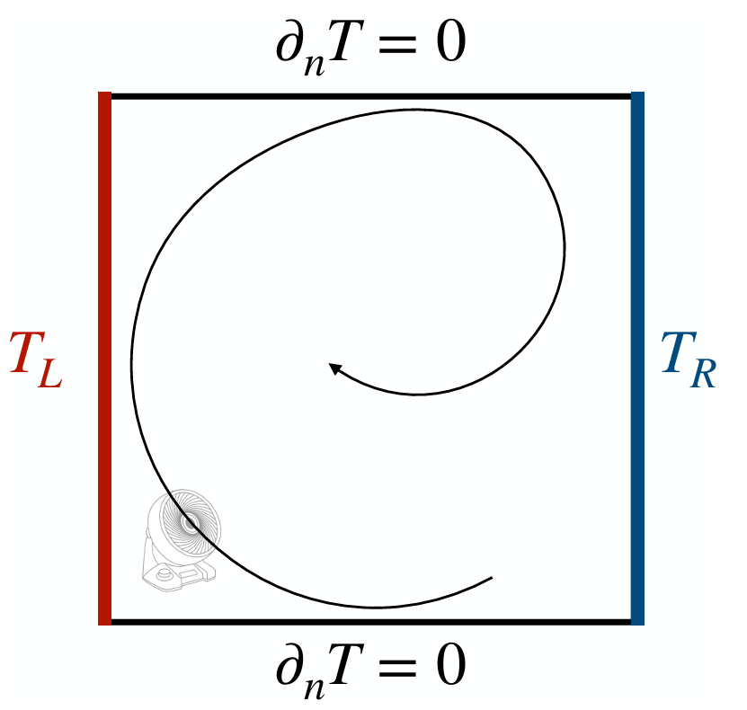
v = U0 cos(πx) sin(πy)
Numerical method
A conservative finite-volume formulation
Face fluxes transport heat through every control volume while ghost cells impose the thermal boundary conditions.
Advection
First-order upwind face values maintain a stable and bounded temperature field.
Diffusion
Second-order central gradients represent the constant-diffusivity thermal fluxes.
Time integration
Forward Euler advances the transient solution with a combined advection-diffusion stability restriction.
Stationarity
Near steady state is accepted after the maximum temperature-change rate remains below 10−6 over repeated checks.
Transient transport
The vortex bends the temperature field
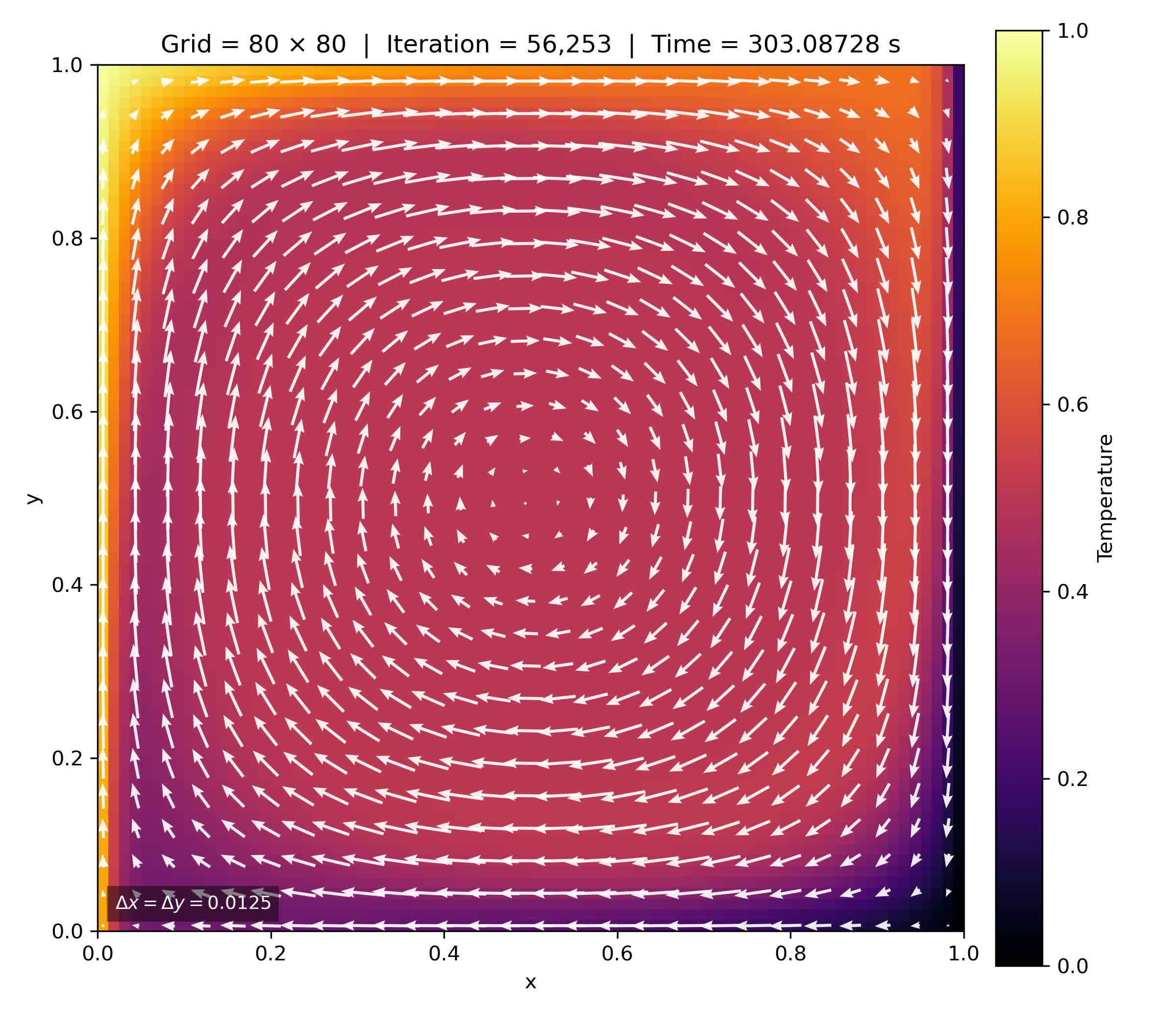
Heat enters through the left wall and is carried around the cavity by the imposed circulation.
Warm fluid travels toward the upper and right regions while colder fluid returns toward the hot side along the lower part of the cavity. Diffusion smooths the field and forms the wall gradients.
Grid convergence
Four grids, one refinement trend
Refinement sharpens the near-wall gradients and reduces the visible numerical diffusion of the first-order upwind scheme.
Low-cost overview with broad thermal gradients.
Clearer boundary layers and stronger internal detail.
Smooth contours close to the finest-grid behaviour.
Reference case with the most resolved wall gradients.
Practical conclusion
The 60 × 60 and 80 × 80 fields show only small visual differences, indicating that the solution is approaching practical grid convergence.
Engineering outcome
A verified solver for coupled transport
The project combined conservation, numerical stability and grid refinement in one transient thermal model.
It demonstrated how imposed circulation reshapes heat transfer and how increasing resolution improves the representation of thermal boundary layers.